PCB or Printed Circuit Board is pretty much universal. It is found in most devices you use on a daily basis, such as computer, television, radio, etc. PCB is a traditional term for a bare board that is used to automatically support and connect electrical components. This is done through conductive signal tracks carved from copper sheets to non-conductive point-to-point wiring. It creates a highly durable connection and can be changed easily.
Unlike the usual ways of creating electronic parts, printed circuit board offers great advantages to users. It is more organized whereas before each wire is placed anywhere it could fit. A total mess.
For you to understand more what PCB is and how it works, let’s get it started.
Printed Circuit Board
As explained above, the PCB or Printed Circuit Board is basically a board that contains different lines and pads. These support and electrically connect multiple wiring components via small pathways, called traces. The board allows power and signal to be transmitted from one device to another. PCB fits multiple components in a small amount of space.
Different PCB Parts

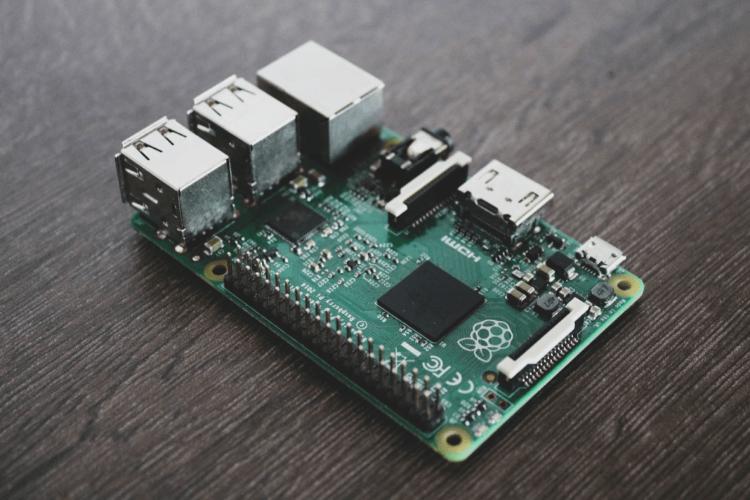
Image source: https://pixabay.com/photos/technology-information-industry-3376792/
Just like the human body, a PCB consists of several integral parts. These parts work hand-in-hand to manage electric current. Printed circuit boards keep everything in place and connected in a form that is simple and easy to utilize. Now, let’s get to know different parts of a PCB.
Resisters
These small parts that look like a horizontal cylinder limit the flow of electric current through a circuit. They often come in five colored stripes which help the user identify their level of resistance. They also have schematic systems that provide such information printed in words.
Circuit Boards
These are thin polyester films that are mostly blue or tan in color. They have multiple layers of conductive copper foil, regardless of the color. Circuit boards themselves are not complicated at all. You can also buy pre-carved boards. You just need to know the right size for your needs and case.
Connectors
These connect your device to other devices as well as to other circuit boards under the same apparatus. A picoblade connector is one great example. Generally, connectors have plastic shells and several pins. These pins act as links between a device and other cables.
Potentiometers
These resistors are often marked in three digit ohms (an electrical resistance between two points of a conductor). They also have a letter code that is used to indicate the change in resistance.
Copper
It is a thin copper foil layer etched to the board with adhesives and heat. The thickness of a copper can differ and is determined by weight (ounces per square foot). Each ounce equals to 35 micrometers of copper thickness.
Silkscreen
This adds numbers, letters, and symbols to the PCB that make it easier to assemble. It also serves as an indicator for humans to easily understand the board and to indicate the function of each LED. The silkscreen is often white though there are other colors as well.
LED
Light emitting diode (LED), is a part that produces light. It can be in a high or low-powered type with single or multiple colors. Though, the most common type is single colored with low-power. LED has two terminals — anode and cathode.
Relays
These are electronic switches that are open when detached relays are closed. These often have plastic shells with written classifications and a letter “K” for relay labeling. There are specifications written on them, as well.
Integrated Circuit
IC or integrated circuit is often marked as “IC” or “U” on most circuit boards. It can be pretty challenging to correctly identify this type of circuit since different types of ICs may come under the same package. Users need to look up the datasheet for more information.
Oscillators and Crystals
These act as natural clocks that keep electronic devices work real-time and error-free. They are marked on circuit boards with an “X’ or “Y” and often have a unique appearance that makes components easy to identify. Specifications are also written for additional information.
Transistors
These are switches that are identified by their three terminals and are in “D” form. Transistors are marked with “Q” on circuit boards. They have three leads in which one point goes directly to a bar, while others go diagonally and contain an arrow.
Let’s Assemble a PCB

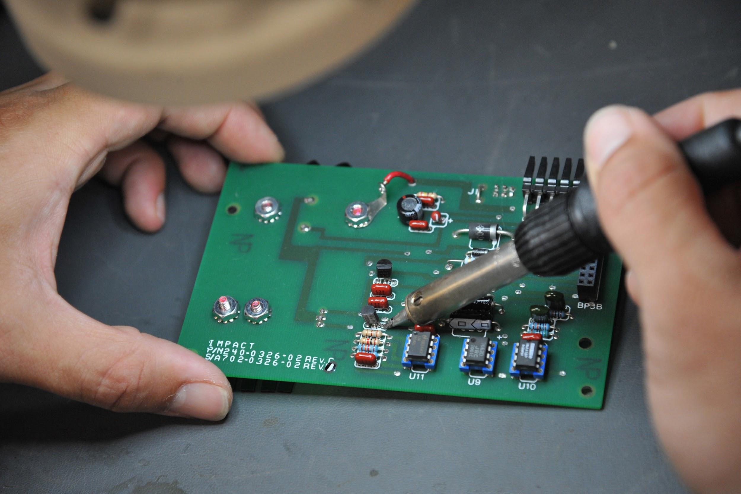
Image source: https://www.seymourjohnson.af.mil/News/Article-Display/Article/307148/save-a-million-call-afrep/
To assemble a PCB, components are connected to the circuit board in different manners. A schematic pattern is followed using numbers on the silkscreen and solder to attach the components to the circuit board. You should be very careful when soldering since solder is a metal you need to melt. It can cause accidents if you don’t practice proper handling.
Moreover, any metal components or stray blobs that are disorganized can easily touch other metals and could cause a short circuit. This can also lead to greater damage, such as fires or small explosion. PCB is ready to use in a device when all metal components are properly installed. Most of this process is automated, with millions of circuit boards being manufactured globally for electronic device use.
Conclusion
These are some important insights you need to know about PCB. It may look uncomplicated to the naked eye, but the entire process can be extremely complex, especially with advanced devices. However, if you know the basics, then you’re safe.
The standard components will remain the same, even with 15 or 20 layered circuit boards. If your design is popular, you have the opportunity to sell it. You see, there is more to these circuit boards that meet the eyes. There you have it! I hope you learn something about PBCs.


